
Phone Repair Images Must Keep Connector Labels Legible
A repair guide can fail because one photograph is almost clear. The arrow points near two sockets, a ribbon cable label fades into glare, or the board has been rotated between steps. A reader follows the image, lifts the wrong connector, and turns a cosmetic cleanup into a hardware mistake.
An AI image tool can reduce bench clutter and improve contrast, but a phone-repair image has to preserve orientation and component identity. The cleanest board is not automatically the most useful frame. It is the frame that lets a reader match the instruction to one physical connector.
PicEditor AI provides enhancement, object erasing, relighting, upscaling, and text-oriented workflows for common image files. Treat every output as a draft. Tiny board labels, screw positions, cable edges, and tool contact points need a source comparison before publication.
Create A Connector Map Before Cleaning The Bench
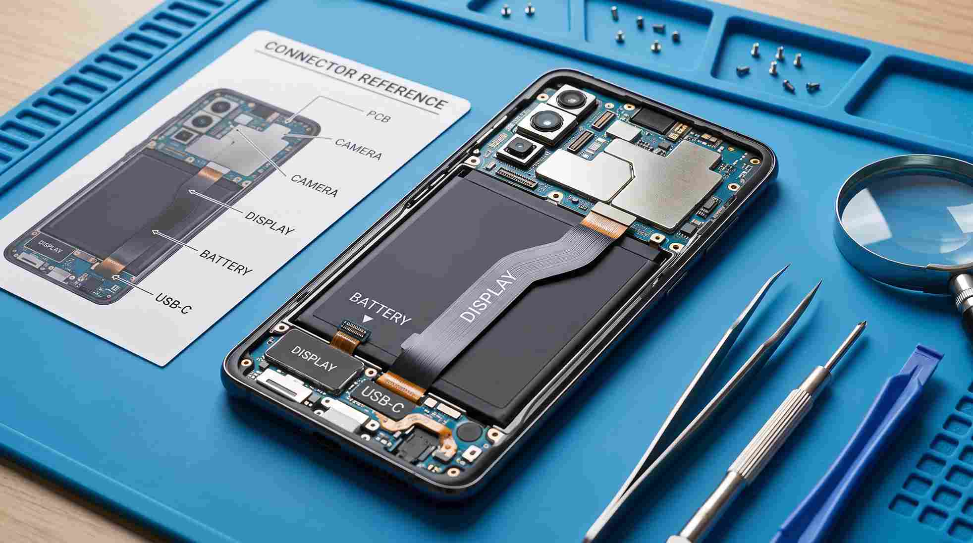
Photograph the full device first. Keep the top, bottom, hinge, camera cluster, or another unmistakable landmark visible. Then assign simple reference names to connectors and screws. These names should match the written steps and remain outside the generated image as editable labels.
Fix One Orientation Across The Whole Guide
Choose battery at the bottom, cameras at the top, or another rule and keep it. If a close-up must rotate, add an explicit orientation cue. Do not flip the image for composition in an AI Photo Editor; mirrored boards turn left and right instructions into hazards.
Photograph Before And After Each Disconnect
A paired frame shows the cable attached and then safely released. Keep the camera position stable so the reader can identify what changed. If several connectors are already open in the first close-up, the guide cannot prove which action belongs to the step.
| Detail | Must remain visible | Failure signal |
| Ribbon connector | Socket edge and cable path | Cleanup blends cable into board |
| Screw group | Every occupied and empty hole | Patch invents or removes a screw |
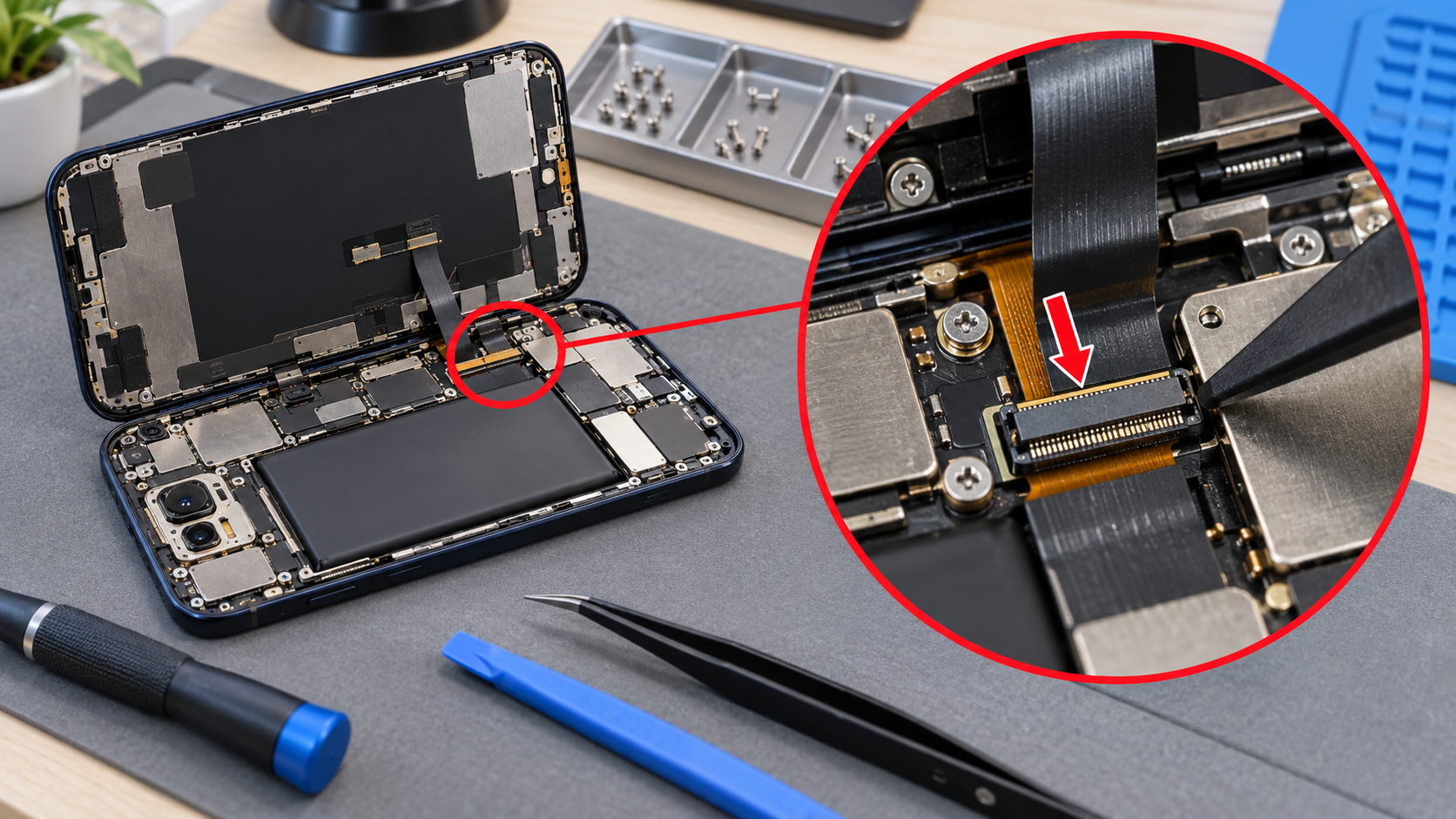
| Tool tip | Contact point and angle | Arrow points between two parts |
| Board marking | Original glyph shape | Enhancement creates readable fiction |
The map gives reviewers a stable basis for checking captions and arrows. It also exposes when one photo cannot carry enough detail and a second angle is safer than stronger enhancement.
Keep a screw card or parts tray in a separate reference image when removal order matters. Do not add the tray to the board close-up or ask enhancement to make tiny labels readable. One photograph should answer one question: where the part sits, how it disconnects, or where it is stored.
Record the device model and visible board revision outside the image. Similar phones can route cables differently even when their shells match. The photograph documents the unit on the bench; the caption tells readers which hardware the step was verified against.
Follow Four Steps For Clear Repair Images
Work through capture, crop, cleanup, and annotation in that order. Each stage has a different purpose. Combining them in one generative request makes it difficult to tell whether a connector changed while the bench became cleaner.
Step One Captures A Wide Orientation Frame
Show the device shell, board location, and nearby landmark before moving close. Use even light and avoid reflections from a bare lamp. The wide frame gives the reader a route from the opened phone to the detailed step.
Step Two Crops Without Removing Landmarks
Crop close enough to show the target but leave one known feature in view. A camera module, battery corner, shield shape, or printed code can anchor orientation. If no landmark fits, pair the close-up with a small inset from the wide frame.
Step Three Cleans Only Outside The Device
Use a tight mask for dust, loose packaging, or tools that are not part of the instruction. During the photo editor AI pass, do not generate over the board, cable, screw holes, seals, or adhesive. Bench polish is never worth changing repair evidence.
Step Four Adds Conventional Arrows And Labels
Place arrows in an editable graphics layer after the photograph is approved. Keep the tip on one component, leave the label outside dense board detail, and use the same naming scheme as the written instruction. PicEditor AI should not render tiny technical labels that later need exact correction.
An AI Photo Editor can improve visibility, but upscaling cannot recover a marking that the camera never resolved. If a board code matters and remains unreadable, capture a sharper macro photograph instead of accepting a convincing reconstruction.
Watch adhesive and seal edges during cleanup. A faint line may show where a battery tab begins or where a water-resistance seal must remain intact. Removing it as dust can make the guide less safe. Protect those edges on the connector map before opening any cleanup mask.
Match Every Arrow To The Physical Connector
Print the guide or open it on a second device beside the actual phone. Start from the wide view and locate each target in order. Confirm connector shape, cable direction, surrounding screw pattern, and board orientation before reading the caption.
Run A Novice Connector Pointing Test
Ask someone who did not edit the images to point at the part described by each step. They should identify one component without explanation. Hesitation between two nearby sockets means the crop or arrow needs revision, even if an experienced technician can infer the intent.
Overlay Candidate And Source At Half Opacity
Align the connector edge and toggle the images. Screw holes, printed traces, shield corners, and cable paths should not jump. A small exposure difference is acceptable. A shifted contact, duplicated screw, or smoothed cable edge is not.
Keep a short record of image adjustments with the source photographs. Readers need the correct part, safe action, and orientation; if a revised image introduces confusion, the technician can return to the camera file and rebuild the annotation from a verified view.
Review the guide in the order someone will perform it. A later photograph may reveal that an earlier cable should still be connected or that a shield appears too soon. Sequence errors can survive perfect individual images. Compare the physical device after every step and reshoot when the state no longer matches.
PicEditor AI is most useful for cleaning the space around a well-captured target. A photo editor AI cannot compensate for an arrow that crosses several components or a camera angle that hides the latch. Improve capture and annotation first, then apply restrained visual cleanup.
Publish Images That Reduce Repair Guesswork
A useful guide gives the reader a reliable path from the whole device to one connector. It does not ask enhancement to replace macro photography or let a clean bench hide changed board details.
Keep the approved source set beside the final guide so a correction can begin from the camera file. That archive matters when a later device revision moves a connector or changes a shield.
Map the components, keep orientation fixed, and test every arrow on the physical device. That makes edited repair images clearer while leaving the hardware evidence intact.